Keyboard Design Part 2 - Schematic Symbols and Footprints
Designing a wholly integrated keyboard PCB from the ground up can be a tough ask. That's why I started by integrating an existing development board into a "carrier" PCB that I designed and ordered. That project can be found here.
The concept of using a devkit to build a keyboard isn't new. People in the hobby have used the Pro Micro from SparkFun for years to iterate quickly and to do away with some of the complications of having a fully integrated board assembled. The Pro Micro's history in the hobby has also meant that a number of other devkits with extended functionality are available with Pro Micro backwards compatibility.
To get started, let's take a look at the microcontroller development board we'll be using!

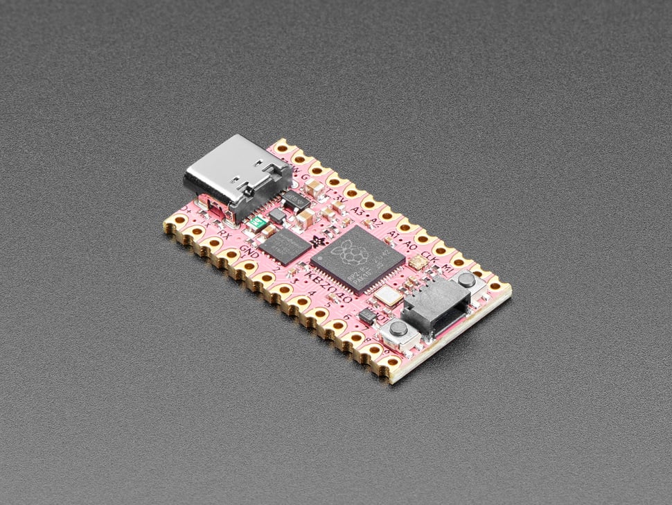
The Adafruit KB2040 integrates an RP2040 from the Raspberry Pi Foundation (yes, that Raspberry Pi) into a Pro Micro footprint. Some other fun bells and whistles include 16MB (!) of flash, an addressable RGB LED (or NeoPixel), and STEMMA QT support. For more information on STEMMA QT (which is really an I2C bus + power in a JST connector) check here.
I have chosen this board because of its availability and the popularity of the RP2040 in the hobby at the time of writing. The RP2040 has been available when few other microcontrollers have. The flash size mentioned above also enables keyboards based on the RP2040 to store dozens of layers, macros, and other fun QMK features you will be introduced to soon.
Let's get started. Open up KiCAD (check here for installation instructions from the last post) and create a new project.

You will see two files generated by creating this project:

Start by opening the "*.kicad_sch" file. You will be greeted with a blank schematic. Unlimited possibilities!

To get started, let's place a Pro Micro schematic symbol. You may notice that we don't actually have a "Pro Micro" schematic symbol or footprint. Fret not! A key part of learning an ECAD suite is picking up the ability to generate good looking and functional schematic symbols and footprints.
Note: skip ahead to simply download the KiCAD symbol and footprint I will show how to design. I encourage you to try it out yourself as you will almost certainly discover a part with a poor schematic symbol or incorrect footprint.
The Pro Micro's pinout is relatively simple. To get started, let's look at the Adafruit KB2040 documentation.

The specific pins broken out can be seen in the pin headers on the left and right.

Lets create the schematic symbol! Open the Symbol Editor from your project in KiCAD.

Click "File > New Library" and create a Project specific library. You can also create a global project library if you intend to use this symbol in other PCB designs.

Name the library "Pro_Micro.kicad_sym" and save.

Click the "create a new symbol" button in the top left.

In the "New Symbol" dialog, add the symbol name ("Pro_Micro") and leave everything else default.
Now it is time to create pins that match the pinout above.
Tip: Use the shortcut "Shift+P" to place pins.

There are a ton of options here! Leave most as default. Let's name the first pin "D+" to match up with the pinout and set its number to 1. Make it a "Passive" pin under "Electrical Type."
Continue assigning pins! We will add their layout shortly. This should be the result you see. Note: the right row starts with 26 because it will be used with the footprint generation wizard later.

Tip: While moving a pin with the mouse, press "x" to mirror it horizontally.
Tip: While moving a pin with the mouse, press "y" to mirror it vertically.

To flip the right side pins, I select them all and press "x."
It is a best practice for your schematic symbols to place their power pins on the top and their ground pins on the bottom.

To simplify your schematic, place pins that have identical functions (like GND) over each other with all but one pin being set invisible like so.

When invisible, pins look grayed out.

Stack them over eachother.

Next add a rectangle with the rectangle tool on the right side tool bar.
Be sure to set your grid size to 0.05" (1.27mm)!

Select the rectangle and set its "Fill Style" to "Fill with body background color."

Save! You are now the owner of a fresh new pro micro schematic symbol.
Now time for the footprint.

Look specifically at the sides of the KB2040. You will see that there are two ways to actually mount the device. The little "scoops" beside the pin holes are called castellations (because of their resemblance to the notches on a castle wall) and can be used to surface-mount the devkit. For now, lets just use the through holes with commonly available 0.1" (2.54mm) spaced pin headers.

To begin, open the footprint editor.

Next, click the "Footprint Wizard" button. It is a DIP chip with a star icon.

Select the S-DIP generator.

Using the above mechanical drawing, set the S-DIP generator settings to the following.

This corresponds to the 26 pins of the pro micro, the 2.54mm spacing between them, and the 15.24mm distance between the two rows of pins.


Next, click the "export to editor" button. I would recommend rotating the footprint to sit vertically, but it doesn't really matter.

Click "New Library..." upon saving the footprint. Rename it to Pro-Micro when saving.

Add a library to the project's scope. Name the library something like "Pro-Micro.pretty."

You should see something like this.
Go ahead and update your schematic symbol to refer to this specific footprint.

Open the schematic editor, select the Pro-Micro schematic symbol you just created, and click the "display symbol properties editor," button.

Click the footprint box and select the Pro-Micro footprint you just created. Congrats!
The process for creating any symbol and footprint is mostly the same! Don't be afraid to make the symbols you need when doing any project--it is certianly fine to use something like SnapEDA's library but you should be able to make modifications to footprints if necessary.
Here is the GitHub repo with the example pro micro footprint and symbol!
Thanks for reading. Next up--a custom macropad using the pro micro!
For more information and to ask keyboard specific or general electronics questions join our Discord!


