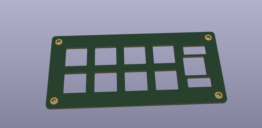
Keyboard Design Part 5 - Plate Design
Remember the Keyboard Layout Editor .json file we saved earlier? Turns out that we can use it to generate a plate file! Let's make a simple stand-off based plate for our macropad.

To get started, navigate to the ai03 Plate Generator site.

Paste your KLE file into the text box. If you don't have one, check out Keyboard Design Part 3.
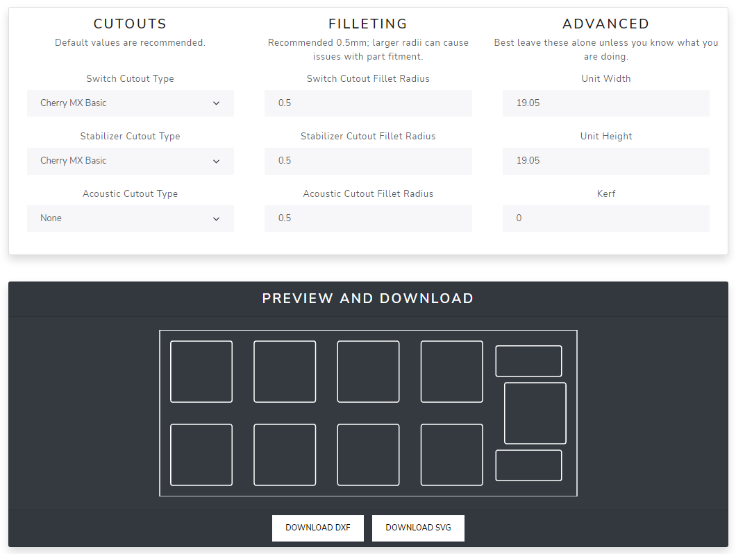
The following plate file will be generated for you. If you are using a different variety of switch, change it from Cherry MX to whatever you have chosen for your PCB.
Caveat: watch out for the orientation of your stabilizers!
If you have a stabilizer oriented on your PCB like this (south-facing) you should use the following stabilizer cutout and footprint combination:
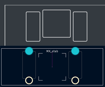
If your footprint is flipped, i.e.

Then simply flip your stabilizer cutout by adding "_rs:180" to the spacebar's footprint in the keyboard layout description.

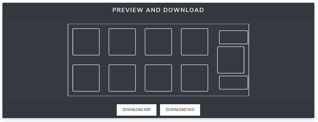
We will now download the ".dxf" file from ai03's plate generator. This can be used in CAD programs like SolidWorks or Fusion360 but can also be imported directly into KiCAD. We will use KiCAD to create a plate that can be manufactured by JLCPCB!
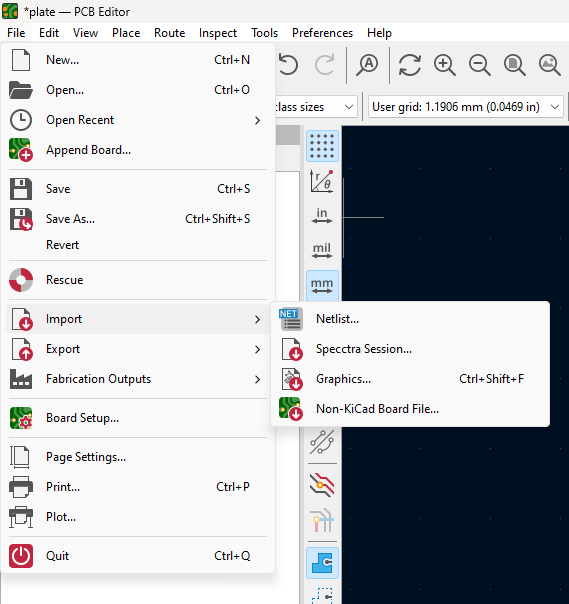
Create a new blank PCB file and click "File > Import > Graphics..."
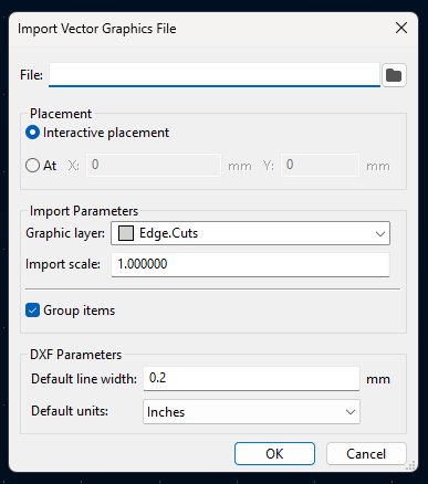
Select and import your file. Be sure to change the "Graphic layer" setting to "Edge.Cuts."

Congrats! Now comes the gross mechanical design part of the process.
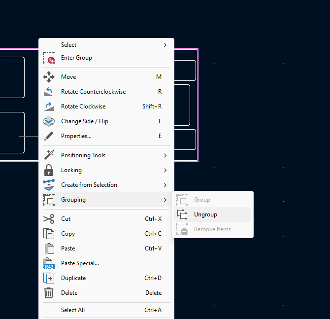
Ungroup the items you just imported by clicking on the group, right clicking, and selecting "Grouping > Ungroup."
Adjust the outlines of your plate by creating a new rectangle. You will use this to add mechanical holes to place standoffs in, kind of like a CannonKeys Practice series board.
Typically, standoffs are M2.5 or M3. I use M2.5 most of the time. Let's add some mechanical standoff holes!
Press "Shift+A" to directly add footprints. Search for M2.5 and select whatever looks nice! I selected "MountingHole_2.7mm_M2.5_DIN965_Pad"
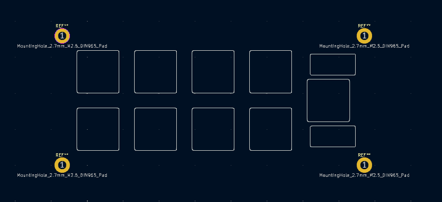
Add a rectangle on the Edge.Cuts layer to outline these holes.
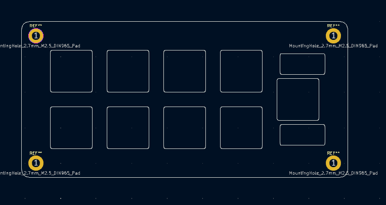
Got it! I would delete the silkscreen layer text so that it doesn't show up on the manufactured board.
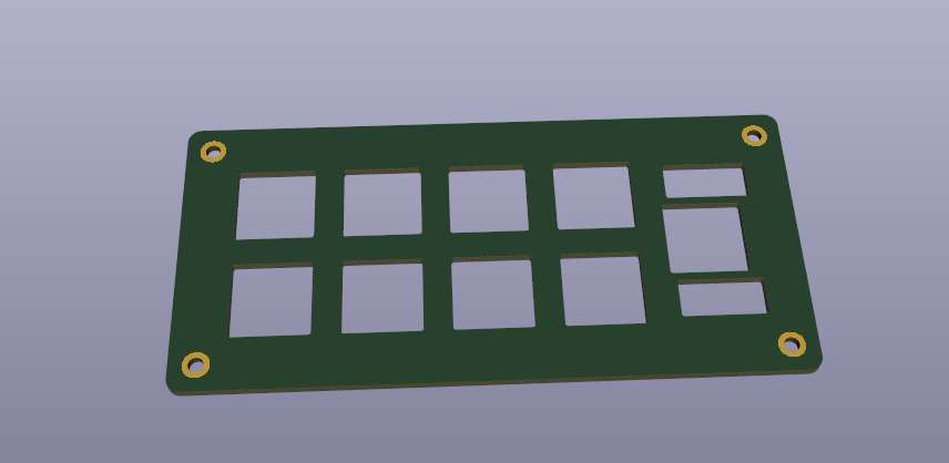
Here ya are!
You can use JLCPCB tools to generate the gerber files for this and order it. It is a best practice to use this in conjunction with a CAD tool to confirm your design if implementing into a machined or 3D printed case.
Hope you enjoyed this post. Join our Discord if you have any questions!
